How to monitor backup power and battery status?
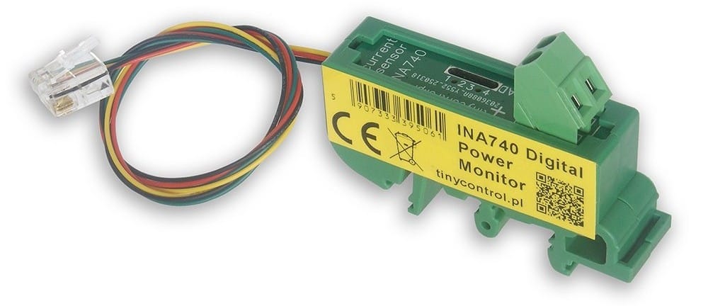
Use the INA740 digital power monitor with your LK4 or LK3.9 controller
System overview: A rack cabinet equipped with a backup power supply and a battery bank.
Objective: Monitor key power parameters to ensure uninterrupted operation of the IT infrastructure.
Why INA740?
The INA740 is a digital DC power monitor that communicates over the I²C bus. Compared to traditional shunt-based analog measurement solutions, it offers several advantages:
- Accurate measurement of current, voltage, power and energy.
- A digital communication interface that eliminates analog noise on long cable runs and removes the need for calibration.
- Simple integration with an LK controller.
Connecting the sensor to the controller (LK4 / LK3.9)
- Connect the I²C bus to the RJ12 connector.
- Install the sensor in series with the measured current circuit.
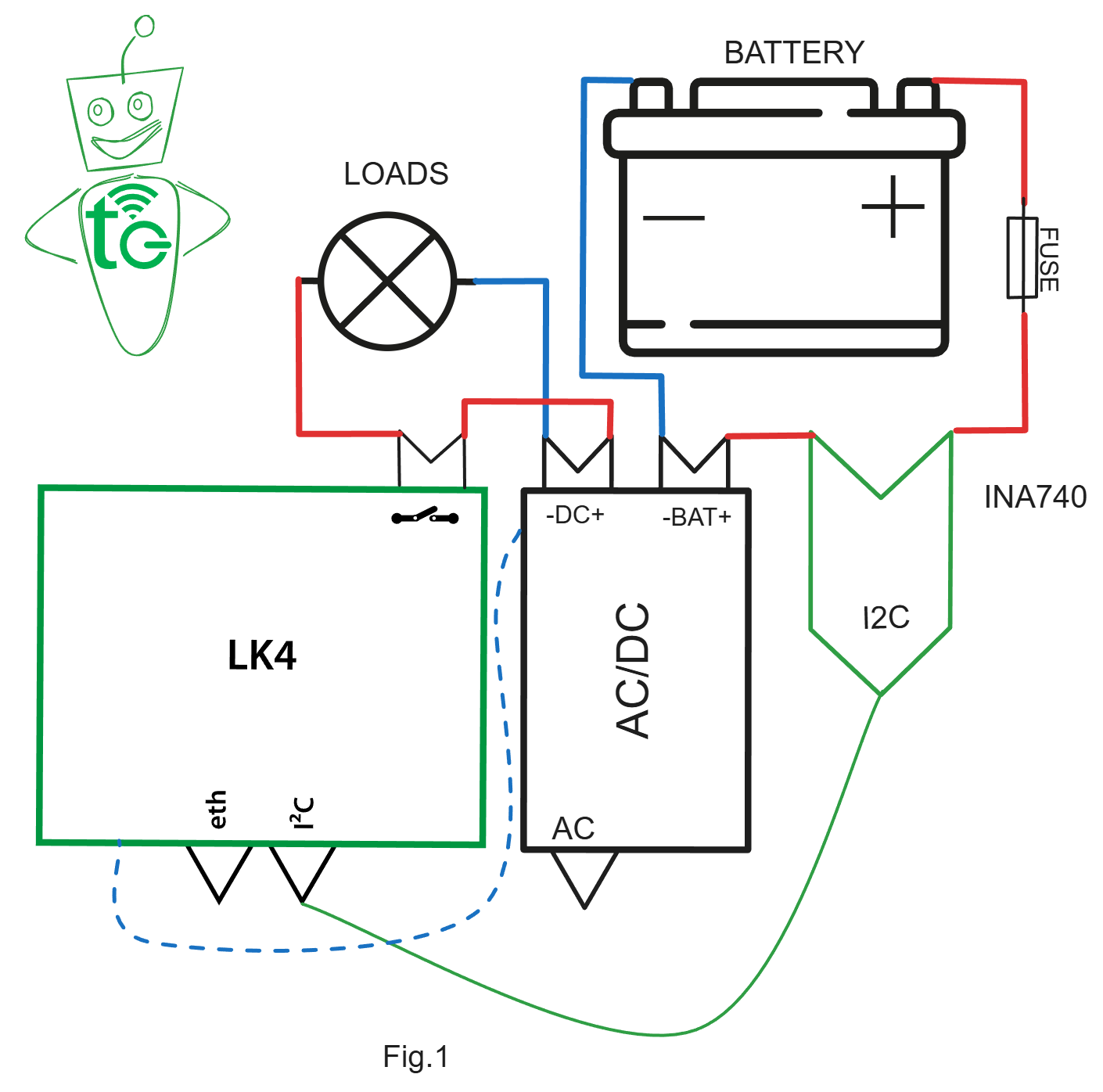
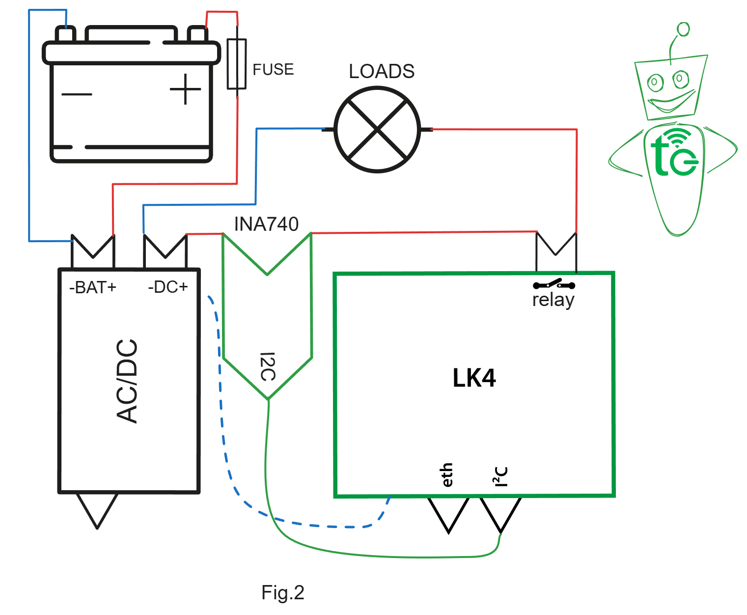
The dashed line shown in the diagrams between the negative terminal (ground) of the measured circuit and the LK controller represents the common ground connection required for voltage measurement. If the circuits are galvanically isolated (which may be required in some applications), only current measurement is possible.
In a typical installation, where the LK controller is powered from the same backup power supply, the ground is shared, allowing both current and voltage to be measured.
Behavior of the two measurement configurations
For the configuration shown in Fig. 1, when mains power is available, the monitor reports a positive charging current together with the battery voltage. During battery operation, it reports a lower battery voltage and a negative current, indicating that the battery is discharging.
| INA740 - Mains power available | ||
|---|---|---|
| Input | Value | Unit |
| Voltage | 13.77 | V |
| Current | 1.54 | A |
| Power | 21.2 | W |
| Energy | 9.27 | Wh |
| Temperature | 45.2 | °C |
| INA740 - Battery operation | ||
|---|---|---|
| Input | Value | Unit |
| Voltage | 13.23 | V |
| Current | -1.52 | A |
| Power | -20.14 | W |
| Energy | 12.42 | Wh |
| Temperature | 45 | °C |
For the configuration shown in Fig. 2, when mains power is available, the monitor measures the load current and the output voltage of the backup power supply. During battery operation, it reports the lower battery voltage together with the current supplied by the battery (discharge current).
| INA740 - Mains power available | ||
|---|---|---|
| Input | Value | Unit |
| Voltage | 13.57 | V |
| Current | 1.5 | A |
| Power | 20.43 | W |
| Energy | 0.34 | Wh |
| Temperature | 48.4 | °C |
| INA740 - Battery operation | ||
|---|---|---|
| Input | Value | Unit |
| Voltage | 12.97 | V |
| Current | 1.45 | A |
| Power | 18.82 | W |
| Energy | 0.98 | Wh |
| Temperature | 51.6 | °C |
Configuring the LK controller
Configuration is completed in a few simple steps:
- Open the I²C and 1-Wire Sensors menu and select the I²C tab.
- Enable the INA740 option and save the form. If the sensor is not detected shortly after saving, you can click Detect I²C Sensor to trigger detection manually.
- Once the sensor readings appear in the tables below the form, click Configure mapping to variables m1–m30. Assign the INA740 parameters to the required mX variables as described in the documentation. This allows the sensor data to be used by the LK controller for automation or forwarded to external systems.
- You may also find it useful to select the mapped power reading (mX) as the value for the I field in the Power and Energy tab. This enables energy calculation and allows you to use the built-in functions for starting and stopping energy counting, as well as resetting the accumulated energy value.
When monitoring only the battery (positive/negative current and power), it is theoretically possible to estimate the battery state of charge (SoC). In practice, however, this method is prone to significant errors. For example, after an extended period of mains operation, even a very small charging current can accumulate into an unrealistically large energy value.
A more reliable approach is to reset the battery energy counter whenever a negative current (battery discharge) is detected. By reporting the amount of energy delivered by the battery since the last reset, the system provides a practical indication of battery usage and condition.
Automation and fault scenarios (events and notifications)
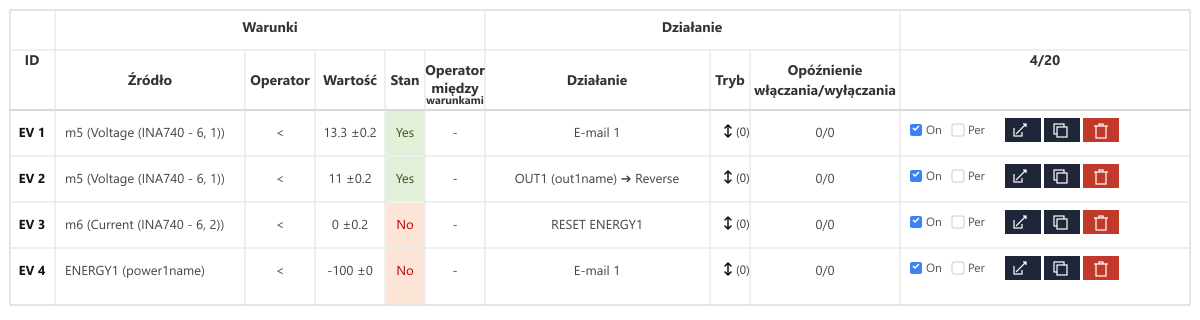
Using the measurements provided by the INA740, the following events (automation rules) can be configured in the LK controller:
- Event 1 (Mains power failure): If the V_IN voltage drops below the backup power supply charging threshold (transition to battery operation), send an MQTT notification or an email.
- Event 2 (Deep battery discharge): If the battery voltage falls below a critical level, disconnect the OUT output (for example, OUT6) to protect the battery cells from deep discharge damage.
- Event 3 (Reset battery energy counter): When a negative current is detected, reset the battery energy counter.
- Event 4 (Battery discharge alarm): After the battery energy counter has been reset, send a notification containing the discharged energy value.
As these examples demonstrate, automation can be used not only to control physical outputs, such as disconnecting a load, but also to send notifications from the LK controller using various Internet protocols. The protocols supported by each controller model are listed in the corresponding technical documentation.
Monitoring and remote management
Current, voltage, and other measured parameters can also be sent to remote servers using protocols such as SNMP, HTTP, and MQTT.
tinycontrol provides a free MQTT server for collecting measurement data. Simply register at mqtt.ats.pl and add your LK controller. Sensor readings can then be uploaded every five minutes and viewed remotely as charts.
When switching elements are connected to the LK controller, such as relays, they can also be controlled remotely via MQTT, for example using a mobile application.
Benefits of using the INA740 power monitor with LK IoT controllers
- Simple hardware setup with measurement of the most important electrical parameters and temperature.
- High measurement accuracy.
- Flexible automation and notification configuration.
- Remote monitoring with historical charts for system analysis.
- Remote management capabilities.