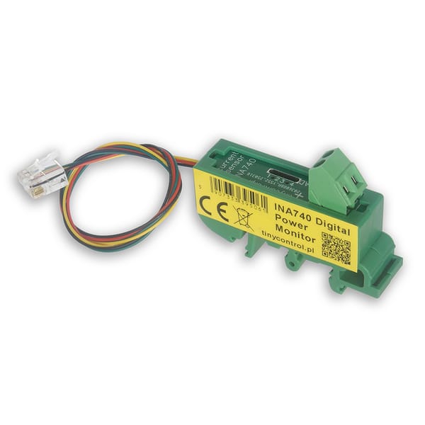
How to ensure proper temperature and humidity in IT cabinets – local control and remote monitoring
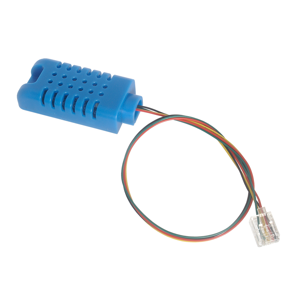
Use the AHT20 sensor and connect to LK3.9 or LK4
Example installation: A rack cabinet or a small telecommunications cabinet equipped with IT equipment, a fan, and a heater (for outdoor applications).
Objective: Monitoring temperature and humidity, with automatic control to ensure reliable operation of the IT infrastructure.
Equipment used
 tinycontrol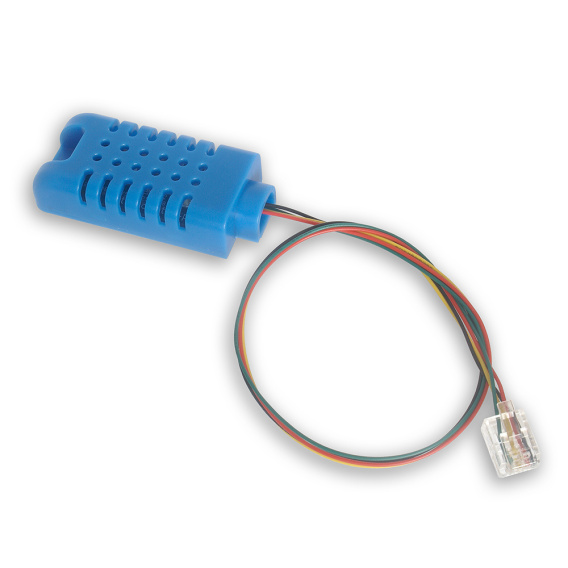
 tinycontrol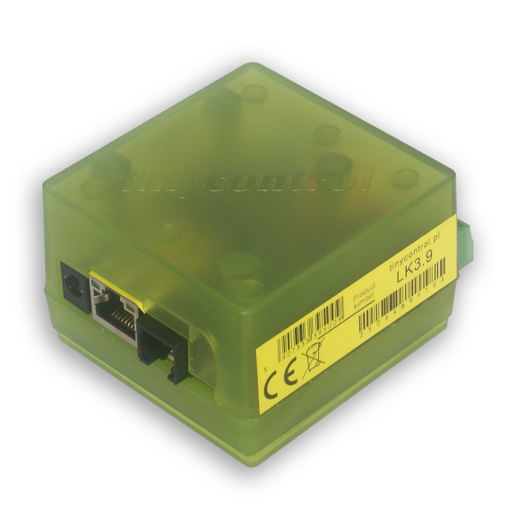
- actuators: heaters, fans.
Benefits of this solution
- Sensor:
- easy installation
- digital sensor data bus requiring no calibration
- high measurement accuracy and repeatability
- Controller:
- universal Ethernet interface for data transmission
- multiple protocols for monitoring and sending data to a server
- alarm notifications when configured limits are exceeded
- built-in control automation
- option to connect additional DS18B20 temperature sensors
- intuitive configuration via the built-in web interface
Installation
The sensor should be installed in a location with airflow inside the cabinet, e.g. on a vertical structural support used for mounting shelves.
It should not be mounted on equipment that generates heat.
Connection
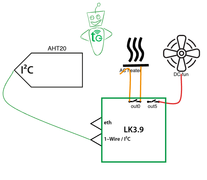
Connect the AHT20 sensor directly to the RJ12 socket.
A DC-powered fan operating at the same voltage as the LK power supply can be connected to OUT5 (transistor output – current consumption below 0.75 A). The OUT0 relay is also available, e.g. for switching a heat source. Additional relays can be connected to the OUT1–4 outputs of the LK3.9, for example using a relay board.
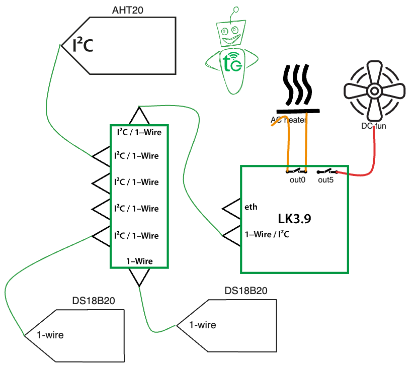
Additional DS18B20 sensors should be connected via a splitter, which distributes both the I2C and 1-Wire buses.
Configuration
In the I2C and 1-Wire Sensors tab, select AM2301B/AHT25/AHT20 as the primary sensor and confirm by clicking Save. Sensor readings are available as T1/H1 in the Inputs tab, and these variables should be used when sending data to a server. Additional DS18B20 sensors must be connected one at a time so that their identifiers can be read and saved in selected positions with custom names. Their readings will then be displayed as DS1, DS2, etc., also in the Inputs tab.
Sensor readings can be sent using various protocols, such as HTTP, MQTT, and SNMP. A free account on the mqtt.ats.pl server is available for tinycontrol devices, allowing data to be sent every 5 minutes.
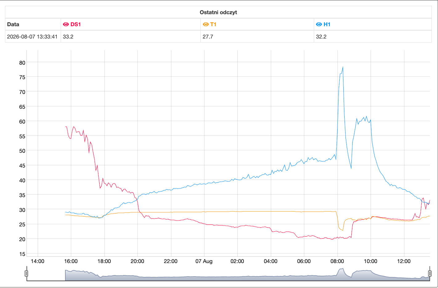
Automatic control setup
To maintain a relatively stable temperature and prevent condensation, you can use the Events function available in LK controllers. By defining threshold values that trigger actions—for example, switching the heater on when a threshold is crossed and switching it off when the value returns below the threshold—you can create a simple control system. The following two conditions are configured as an example:
- EV 1: switch the heater on if the temperature drops below 10°C;
- EV 2: switch the fan on if the temperature rises above 25°C;

Switching the heater on at a relatively high temperature will generally prevent condensation. Alternatively, an additional condition based on the calculated dew point can be used. To do this, compare the current temperature with the calculated dew point and use the difference as the condition for switching the heater on:
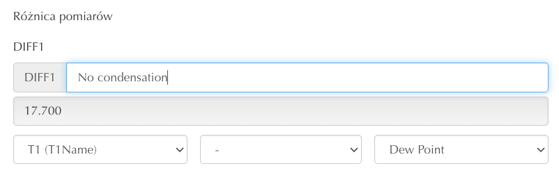

In event EV3, the following condition is configured: if the difference between the measured temperature and the dew point is less than 2°C, switch the heater on.
The user can choose from a range of actions to be performed when a condition is met. This can be a physical action, such as switching a relay, or a notification, such as an email, HTTP message, SNMP trap, or another type of message.
Benefits of using the AHT20 sensor with an LK-series IoT device
- Simple setup for measuring humidity and one or more temperature values.
- High measurement accuracy.
- Ability to configure automation and notifications.
- Charts for analyzing system operation.
- Remote management.